Description
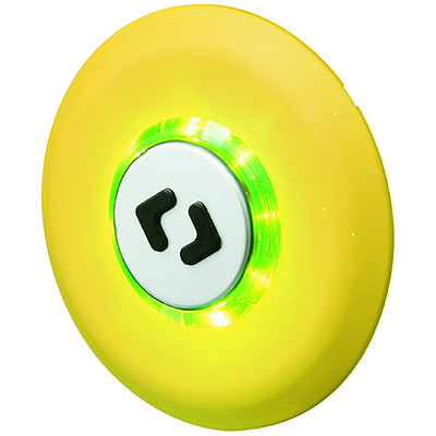
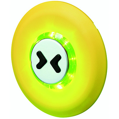
- Momentary switch available in version Standard or as custom specific variant
- Assembly by screws with nuts
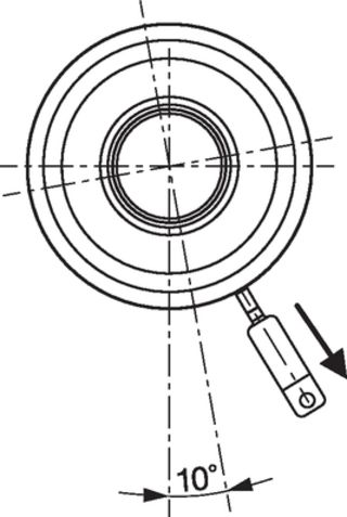
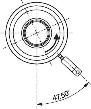
- Four-conductor cable, optional male tabs on housing
Characteristics
- Illumination housing and actuator made of plastic material, cover plate made of aluminium
- Variable color design of the bezel and the cover plate, customer specific laser lettering
- high lifetime with 10 million actuations
Excellent tactile feeling - Illumination for switching status recognition (Viewing angle 180°)
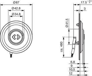
- Low mounting depth with angled cable version
Electrical Data
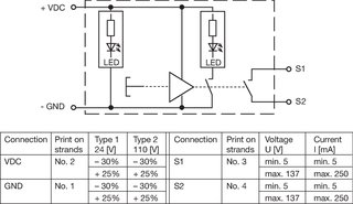
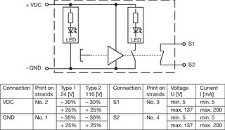
Supply Voltage
LED operating data are listed in separate table
Switching Voltage
min. 5 VDC , max. 137 VDC/ 60 / 50 VAC/DC
Switching current
min. 5 mA, max. 250 mA
Rated Switching Capacity
17 W
Dielectric Strength
8 kV air discharge, 6 kV contact discharge, 500 VAC (VAC 1 min., DIN EN 50155)
Burst Impulse
± 1,8 kV 1,2/50 µs Surge, ± 2 kV 5/50 µs Burst according to DIN EN 50155
Insulation Resistance
> 100 MΩ
Lifetime
> 10 million actuations at Rated Switching Capacity
Mechanical Data
Actuating Force
8 ± 4 N center, 10 ± 5 N edge
Actuating Travel
0.8 ± 0.5 mm center, 1.0 ± 0.5 mm edge
End Stop Strength
250 N
Vibration Resistance
5 h (category 1 class B)
Shock Resistance
30/6 g/ms (DIN 60068-2-27) , 3/5 g/ms (3 vertically and horizontally/ 5 lengthwise, DIN 61373)
Mounting screw torque
0,8 - 1.0 Nm
Lifetime
> 10 million actuations
Climatical Data
Operating Temperature
-40 to +85 °C
IP-Protection
IP67 Front Side, , IP65 Rear Side
Other Data
Fixing Screws
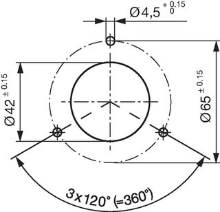
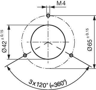
3*M4
Cable Cross Section
4*0.5 mm²
Weight
appr. 85 g
Material
Illumination Housing
PC
Actuator
PC / ABS
Bezel
PBT
Symbols
PC / ABS
Cover of Actuator
Aluminium anodized
Seal Ring
NBR70
Detailed information on product approvals, code requirements, usage instructions and detailed test conditions can be looked up in
Details about Approvals
SCHURTER products are designed for use in industrial environments. They have approvals from independent testing bodies according to national and international standards. Products with specific characteristics and requirements such as required in the automotive sector according to IATF 16949, medical technology according to ISO 13485 or in the aerospace industry can be offered exclusively with customer-specific, individual agreements by SCHURTER.
Application standards
Application standards where the product can be used
| Organization | Design | Standard | Description |
|---|---|---|---|

|
Suitable for applications acc. | EMC Directive: | DIN 55011/55022/50121-3-2/61000-4-3 |

|
Suitable for applications acc. | IEC/UL 62368-1 | Audio/video, information and communication technology equipment - Part 1: Safety requirements |
Compliances
The product complies with following Guide Lines
| Identification | Details | Initiator | Description |
|---|---|---|---|

|
SCHURTER AG | Directive RoHS 2011/65/EU, Amendment (EU) 2015/863 | |

|
SCHURTER AG | On 1 June 2007, Regulation (EC) No 1907/2006 on the Registration, Evaluation, Authorization and Restriction of Chemicals 1 (abbreviated as "REACH") entered into force. |
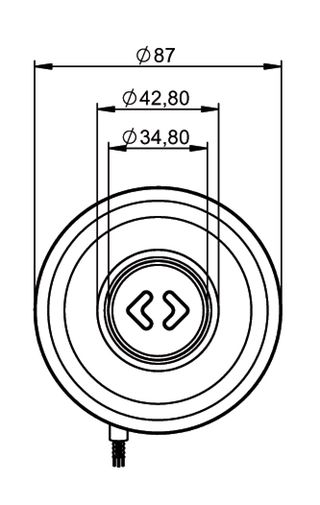
Dimension [mm]
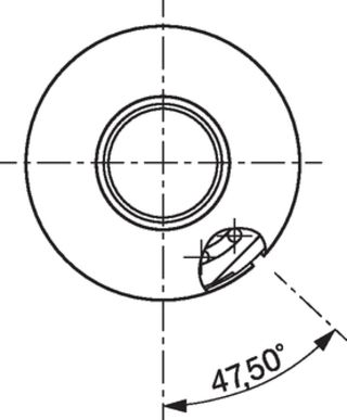
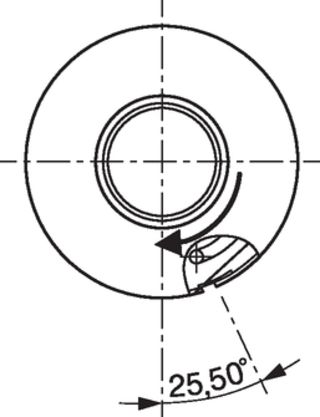
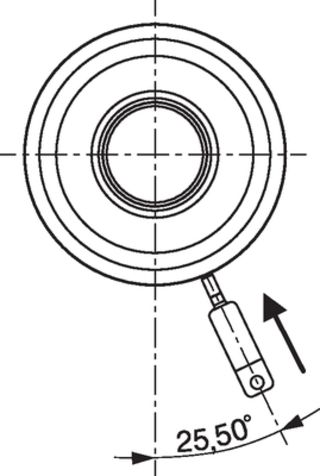
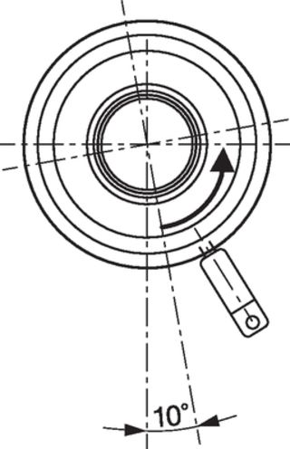
Assembly Instructions
Diagrams
LED Data
| Operating Data | Forward Current typ. | Forward Current max. |
| LED red | 4 mA | 6 mA |
| LED green | 4 mA | 6 mA |
| LED yellow | 6 mA | 8 mA |



 Technical Data